The removal and shaping of both
diseased and sound tooth structure is an essential part of
restorative dentistry.
Initially this was a difficult process accomplished entirely by the use of hand instruments, bulky chisels and excavators
The introduction of rotary, powered cutting equipment was one of the truly major advances in dentistry
The term ‘rotary instruments’ in dentistry refers to a group of instruments that turn on an axis to perform a work such as cutting, abrading, burnishing, finishing or polishing tooth tissues or a restoration.
A handpiece in Operative dentistry is a device for holding rotating instruments, transmitting power to them and for positioning them intra orally. Dental handpiece of today is a sophisticated combination of precision parts moving in perfect synchronization at extremely high speed.
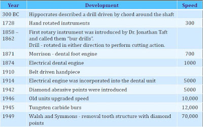
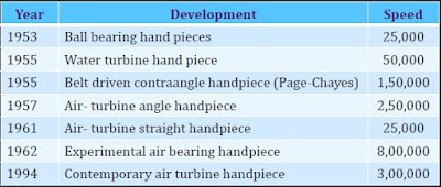
In 1955, a hydraulic driven turbine handpiece was reported to operate satisfactorily at 60,000 rpm.
In the latter part of 1957, the first clinically successful air driven turbine handpiece became available with free running speeds of approximately 300,000 rpm.
1973 – The first high-speed handpiece with fiber optic illumination is introduced.
Quick Question- Suppose if the gear ratio of Red handpiece is 1:5 and Motor Speed is 40,000. What will be the speed at head of handpiece?
Initially this was a difficult process accomplished entirely by the use of hand instruments, bulky chisels and excavators
The introduction of rotary, powered cutting equipment was one of the truly major advances in dentistry
The term ‘rotary instruments’ in dentistry refers to a group of instruments that turn on an axis to perform a work such as cutting, abrading, burnishing, finishing or polishing tooth tissues or a restoration.
A handpiece in Operative dentistry is a device for holding rotating instruments, transmitting power to them and for positioning them intra orally. Dental handpiece of today is a sophisticated combination of precision parts moving in perfect synchronization at extremely high speed.
History of Dental Handpieces
Classification of Handpieces
According to driving mechanism-
- Gear driven hand piece
- Water driven hand piece
- Belt driven hand piece
- Air driven hand piece
- Electric driven (Recent)
Depending upon angulations-
- Straight
- Contra angled
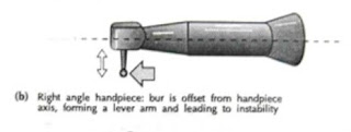
- Right angled
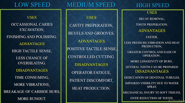
Depending on speed
Sturdevant classification:
- Low or slow speeds (less than 12,000rpm)
- Medium or intermediate speeds (12,000 – 20,000 rpm)
- High or ultra high speeds (more than 200,000 rpm)
Marzouk classification
- Ultra low speed - 300 -3000 rpm
- Low or slow speed- 3000 -6000 rpm
- Medium or intermediate speed - 20,000 – 45,000 rpm
- High speed- 45,000 – 1,00,000 rpm
- Ultra high speed – more than 1,00,000 rpm
Based on head design
- Standard
- Mini
- Torque
Based on bur holding type
- Screw type chuck
- Airmatic bur changer
- Ultrapush system
Based on motor
- AIR TURBINE
- AIR MOTOR
Based on colour coding ring
- Blue–no change in speed
- Green-speed reduction
- Red –speed increase
Handpieces used in endodontic
- Giromatic hand pieces
- Reciprocating hand pieces
- Sonic and ultra sonic hand pieces
- Torque control gear reduction hand pieces
1. According To Driven Mechanism
Gear Driven Handpieces
 |
| Gear Driven Handpieces |
Rotary power is transferred by a belt which runs from an electric engine.
Power is transfered from the straight handpiece by a shaft and gears inside the angle section.
Capable of working at variable speeds though they work best at low speeds because of so many moving parts with metal to metal contact
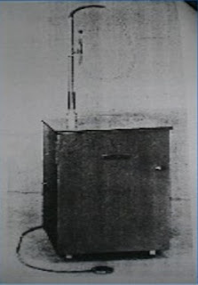
Water Driven Handpieces
 |
| Water Driven Handpiece |
In 1955, a hydraulic driven turbine handpiece was reported to operate satisfactorily at 60,000 rpm.
Two years later the first commercial model called a Turbojet became available.
Improved units have both straight and angle handpieces which will operate at speeds upto 100,000 rpm
Water is conveyed to and from the handpiece by a co-axial type tubing (tube inside a tube)
The small inner tube carries water under high pressure to rotate a turbine in the handpiece head and the larger outer tube returns the water to the reservoir. From here it is recirculated over and over.
The handpiece is extremely quiet and has the highest torque.
Belt Driven Handpieces
 |
| Belt Driven Handpiece |
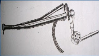
A belt driven angle handpiece called the Page-Chayes became available in 1955 and was the first angle handpiece to operate successfully at speeds above 100,000 rpm.
All gears were eliminated by having a small belt run inside the handpiece sheath over ball bearing pulleys in the angle sections.
Improved models of the belt driven design are the Page-Chayes 909 and the Twin 909.
They have a history of excellent performance and great versatility and free of maintenance.
Air Driven Handpieces
 |
| Air Driven Handpiece |
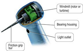
In the latter part of 1957, the first clinically successful air driven turbine handpiece became available with free running speeds of approximately 300,000 rpm.
The air is directed to the head of the handpiece and is blown against the blades of a small turbine to produce rotation while the greater part is exhausted at the back of the handpiece or returned to the control box.
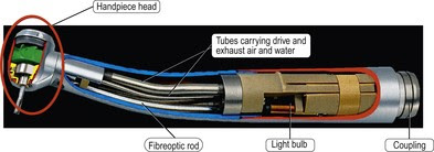
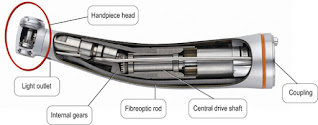
- Provide the operator a source of artificial illumination through the dental hand piece.
- Transmission of light through long, thin fibers of glass or transparent material.
- Each individual fiber is approximately 25 microns in diameter.
- The light travels, non-electrically, through the fiber by reflecting from wall to wall without transmitting or generating heat. This makes fiber optics completely safe for use in the oral cavity
 |
| Fiber Optic Handpieces |
 |
| Parts of Handpieces |
- Rotary vane principle
- Swash plate principle
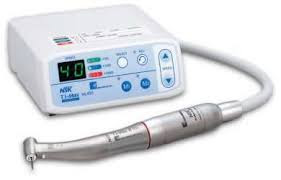 |
| Electric Driven Handpieces |
Most are direct current motors and are
designed with an armature sitting within a permanent magnet
assembly the performance depends upon
- Design and power of the magnetic field
- Design and number of armature coils
- By varying the distance from the magnets to the rotating armature, the speed of the motor can be altered.
The biggest difference in comparing an electric handpiece to
an air driven is its constant speed and less noise.
HYBRID AIR-ELECTRIC HAND PIECE ( ATC)
- ATC refers to Adaptive Torque Control
- This system resembles an electric installation but is referred to as a hybrid, using both air pressure and electricity.
- Uses a sensor in the hand-piece tubing to operate a valve that continuously regulates the amount of air pressure flowing to the turbine.
- Instead of the hand-piece losing power and free running speed – when the bur contacts the tooth, the valve opens , sending more pressure to the turbine to compensate.
2. According To Angulation
Straight Handpiece
 |
| Straight Handpiece |
- long axis of bur lies in same plane as long axis of handpiece.
- Can be attached to micromotor or airmotor.
- It is used in oral surgical and laboratory procedures
Contra-angle Handpiece
- Head of handpiece is first angled away from and then back towards the long axis of the handle.
- Because of this design, bur head lies close to long axis of the handle of handpiece which improve accessibility, visibility and stability of handpiece while working
Air-rotor contra-angle handpiece
 |
| Air-rotor Contra Angle Handpiece |
- It gets power from the compressed air supplied by the compressor.
- This handpiece has high speed and low torque
- Speed range is 1,00,000 to 3,00,000 rpm.
- Used for tooth preparation and removal of old restorations.
- Operates with friction grip burs and diamonds.
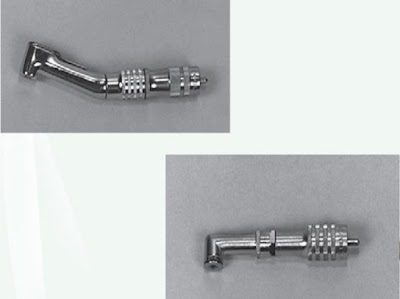
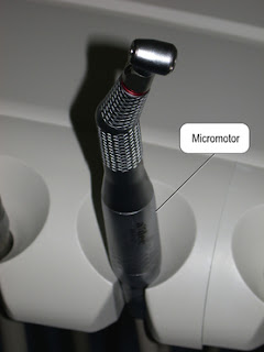
Micromotor:
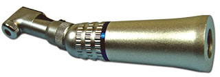 |
| Micromotor Contra Angle |
- It gets power from electric micromotor or airmotor.
- It has high torque and low speed
- Used for finishing and polishing procedures.
Right angled
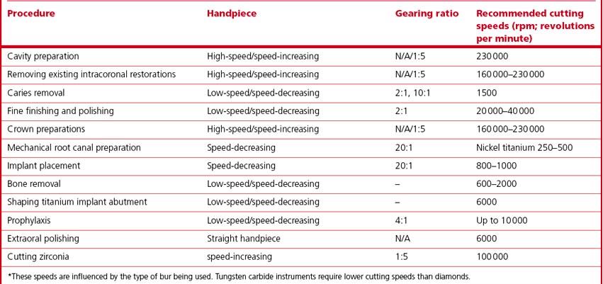
3. According to Speed
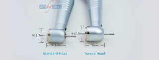
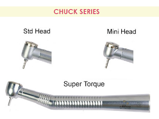
4. According to Head Type (Size and Design)
A small head size improves visibility and access, specially in posterior region.
Larger head size incorporate a larger turbine impellar with more inertial mass that can yield hight output. High Output means more cutting power.
Coding indicates the relative gear ratio of each component and are present in the form of dots/rings.
Blue- No Change in Speed
 |
| Blue handpiece- No change in speed |
Quick Question- Gear ratio of Blue handpiece is always 1:1. If the Motor Speed is 40,000. What will be the speed at head of handpiece?
Red- Speed Increases
 | |
|
 | |
|
Quick Question- Suppose if the gear ratio of Red handpiece is 1:5 and Motor Speed is 40,000. What will be the speed at head of handpiece?
Green- Speed Reduction
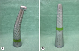 |
| Green Handpiece- Speed Decreasing |
Quick Question- Suppose if the gear ratio of Green handpiece is 5:1 and Motor Speed is 40,000. What will be the speed at head of handpiece?
